Partial Graph Drawing
We provide graphs which are partially laid out. Some of the nodes have specified coordinates, and some of the edges have specified routing points. These nodes and edges are considered fixed. Other nodes and edges have no coordinates and must be laid out. These nodes and edges are free to be moved. All nodes have specified sizes. The task is to find the nicest layout that integrates the free nodes and edges into the layout of the fixed nodes and edges. Note that the fixed nodes and edges should not be moved at all.
The Partial Graph Drawing topic is divided into four categories that will be judged separately. For each category, we provide a data set from a different application domain. The task is to create an aesthetic drawing suitable for the application domain. Manual layout adjustments are allowed, but fully automatic layouts are preferred. For each data set, a separate winner will be determined.
File Format
All data sets use a simple text file format. The following is an example:
|
Fixed nodes are specified as follows:
name,width,height,x,yThe coordinate (x,y) is the center point of the node!
Nodes that are free to be moved are specified as follows:
name,width,height
Fixed edges are specified as follows:
source,target,x0,y0,....,xn,yn
The point (x0,y0) is the connection point at the source node. The point (xn,yn) is the connection point at the target node. All other points (x1,y1) to (x_n-1,y_n-1) are intermediate bend points.
Edges that are free to be moved are specified as follows:
source,target
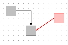
In the sample above, the nodes Id1 and Id2 are fixed, and the node Id3 is free to be moved. The edge between Id1 and Id2 is fixed, and the edge between Id3 and Id2 is free and can be routed. The node Id1 has width and height 40 and a center point at (20,20), that is, the top left corner of node Id1 is at (0,0). The following sketch displays the sample. The black elements of the sketch are fixed, and the red elements are free to be moved.

Data Sets
Simple Tree
The tree has 56 nodes and 55 directed edges. 16 nodes are fixed. The fixed nodes have a minimal spacing of approximately 40 units (border to border). There are no special requirements concerning the edge shapes.
Data File: tree.txt
Org Chart
The org chart has 171 nodes and 170 directed edges. 101 nodes are fixed and 96 edges are fixed. The fixed nodes have a minimal spacing of approximately 40 units (border to border). The edges should be laid out in orthogonal fashion.
Data File: orgchart.txt
Flow Chart
The flow chart has 57 nodes and 72 directed edges. 26 nodes are fixed and 24 edges are fixed. The fixed nodes have a minimal spacing of approximately 40 units (border to border). The majority of the edges should point towards the bottom. Orthogonal edges are preferred but not required.
Data File: flowchart.txt
City Mystery Graph
This is a graph with 391 nodes and 911 undirected edges. The nodes represent cities. The 17 cities of the past Graph Drawing Conferences are fixed on a circle with radius 1500, while the remaining cities are free to be moved. There is no requirement concerning edge shapes or layout style. As an additional task, the contestants should determine what this graph depicts.
Data File: cities.txt

